Progamming Adapters
RoHS
YES


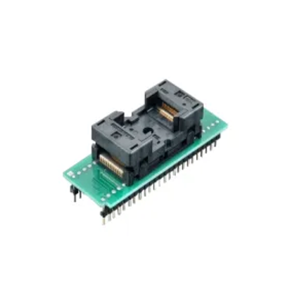
This specialized adapter for STM32 family devices in QFN32 package, has advantage in testingageing, Incoming material inspection,Rework detection, programming on line and on board (PCB).
Main Feature
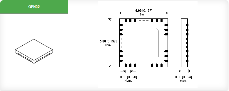
specialized adapter for STM32 family devices in QFN32 package
operating (mechanical) warranty of ZIF socket - 10,000 actuations
supported from PG4UW software version 3.17p,
s/n from 3179-00289 are supported from PG4UW software version 3.76

Protect the contacts of adapter connectors and ZIF socket from contamination. Any dirt and/or fat on contacts may cause errors during programming.
Usage of vacuum pick-up tool is expected for device handling.
Proceed with care! Incorrect insertion of adapter in programmer ZIF socket or device in adapter ZIF socket may lead to programmed device damage.
Insert adapter into programmer ZIF socket. If you are in doubts about orientation of the adapter in programmer ZIF socket, there is a rule of thumb - orientation of adapter name text is the same as orientation of the text on the top of programmer.
Visually check the placement of adapter in programmer ZIF socket.
Push the cover of adapter ZIF socket (the topmost movable part) to open the socket. Insert the device into adapter ZIF socket. Correct position of programmed device in adapter ZIF socket is indicated by picture near (usually on left above) the adapter ZIF socket. On that picture, reference corner of device (e.g. position of pin 1) is indicated by dot, by number 1, by bevelled corner or by any combination of mentioned. Then release adapter ZIF socket.
The cover must be fully actuated (depressed) before inserting a device into the socket. If device is inserted into only partially opened ZIF socket, then - after releasing of cover – device pins might be damaged.
Do not press on device while inserting it and/or releasing the cover.
Visually check the placement of programmed device in adapter ZIF socket. If everything looks OK, the device is ready for programming.
To take out the device from adapter, push the cover of adapter ZIF socket and remove the device.
When you finish the work with adapter, remove it from programmer ZIF socket.
Operating conditions: temperature 5°C ÷ 40°C (41°F ÷ 104°F), humidity 20% ÷ 80% non-condensing.
Functions:
(1) Incoming material inspection
The chip needs to be inspected for quality before use in order to eliminate defective products and improve the SMT yield rate. The quality of the chip can not be seen by the naked eye alone, must be detected by powering up, with the common method of detecting IC current, voltage, inductance, resistance, capacitance can not fully judge the IC good or bad, must be applied through the test socket function to run the program to accurately determine.
(2) Rework detection
Through the test block can save maintenance judgment analysis time to eliminate the causes of bad, reduce the number of motherboard back to solder to reduce the risk of scrap repair board. In addition, the IC in the process of disassembly may be damaged, using the test station can be quickly bad IC sub-check out, the test OK IC reuse to reduce the cost of maintenance collaterals, especially for the unit price of high IC is more applicable.
(3) Burn-in/programming
IC test adapters are installed on the printed circuit board to form IC burn-in holders/IC programming holders/IC adapters, which can be used to program and burn-in ICs or modules by connecting to the appropriate burner.
(4) Ageing test
Component failure mainly occurs at the beginning and the last tenth of the life cycle, aging is through the working environment and electrical performance of the components of the two aspects of the harsh test, speed up the work of the components in the first 10% of its life, and make the defects in the short term, as far as possible to make early detection of failure.
Fields of application:
Cost analysis:
Cost mainly depends on the number of pins, pitch (Pitch), frequency, test requirements (such as temperature, current, life, heat dissipation, etc.) of the IC or module under test, the higher the number of pins, the higher the frequency, the higher the test requirements will increase the cost of the corresponding probe; the higher the number of pins, the smaller the pitch will increase the difficulty of processing the aperture plate and enhance the processing scrap rate, thus affecting the overall price.
Test sockets structure:
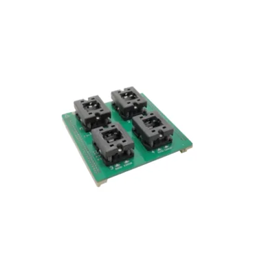
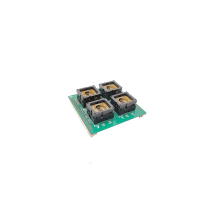
Bounce type: suitable for automatic machine testing of chips or modules, programming, etc., also can be manually pressed or pressed with a booster jig.
Example.
Alloy top window type test holders
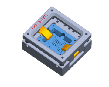
Product features:
▪ Easy to operate, with automatic machine to reduce labour intensity
▪ The special head shape of the POGO PIN pierces the oxidation layer of the solder balls and provides reliable contact without damaging the balls.
▪ The floating plate structure makes it possible to measure ICs with and without balls.
▪ High precision positioning slots and guide holes ensure accurate positioning of the IC or module and high test accuracy
▪ The probe is replaceable, easy to disassemble, cost effective and the metal holder head can be recycled.
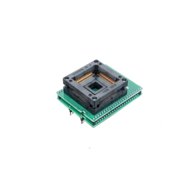
Flip-top type: suitable for manual testing of chips or modules, programming, etc.
Example.
Flip-top screw-on test holders
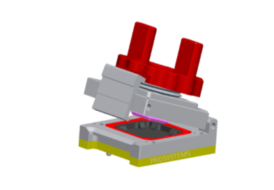
Product features:
▪ Manual flip-top screw-on construction, easy to operate, can be used for chips with a large number of pins
▪ Heat sink or cooling fan can be added to perform long programming tests according to requirements
▪ Floating top cover pressure block with automatic adjustment of the lower pressure to ensure even force on the IC or module
▪ The special head shape of the POGO PIN pierces the oxide layer of the solder balls and provides reliable contact without damaging them
▪ Floating plate structure for ICs with and without balls
▪High precision positioning slots and guide holes ensure accurate positioning of ICs and high testing accuracy
▪The probe is replaceable, easy to disassemble, cost effective, and the metal head can be recycled.
Test Adapter structure material:
Orifice plate, floating plate is the core component of SOCKET, play a fixed probe, guide the role of the chip, limit frame after a large number of tests may appear wear, thus leading to test instability, so there are high requirements for the material, currently on the market commonly used materials are PEEK, ceramic, Torlon, PEI, PPS, FR4, etc., of which FR4 is a common material, the cost is relatively low, easy to FR4 is a common material, relatively low cost, easy to wear, more burrs after processing, is now slowly being replaced.
Probe construction and use:

The probes are normally made of glassy copper with a gold plated outer layer and consist of four parts: the tip, the barrel, the tail and the slingshot;
The mechanical life of a probe is not equivalent to the actual life of the probe, as mechanical tests are carried out using a single probe in a laboratory environment, using vertical downward pressure. In practice, dozens or hundreds of probes are often used at the same time. Because of the precision of the machining of the parts, it is not possible to guarantee that each probe is equal and vertical after installation, and the load on the probes is not always the same, resulting in some probes being damaged prematurely, thus affecting the test life; in addition, the actual application environment often wears out the needles due to dust, chip dross, etc., but the Socket can be extended by replacing the probes However, the life of the socket can be extended by replacing the probe.
Only fully functional probes are capable of reliable signal transmission. The prerequisites for a good quality contact connection are.
▪ accurate probe position
▪no dirt or heavy wear on the tip of the needle
▪no grinding marks on the probe piston
▪no height differences between probes of the same type
▪no bending of the probe
Precautions for the use of the test adapter:
After a period of use, the test adapter may have some residual tin dross and dust at the tip of the needle. If the contamination is serious or contact is difficult, the probe can be cleaned with an anti-static brush or a precision electronic cleaner and the dirt particles scattered inside the test holder can be blown out with an air gun. Large radial forces may cause the probe to bend, do not apply shearing force on the probe when cleaning, do not use corrosive cleaning agents (e.g. Tiana water, board washing water, etc.), otherwise it will bring serious damage to the probe, or even scrap.
When the test stand is not used for a long time, it should be sealed in an anti-static bag and placed in a dry environment to prevent oxidation caused by the storage environment, resulting in poor contact. When using again, the probe should be observed for dirt or oxidation (black), if this phenomenon, please clean or replace the probe before use.